 |
Application of the add-on block library
Function Chart |

(sensitive)
Dynamic test of the basic motion sequence principle of a vertical hose bag
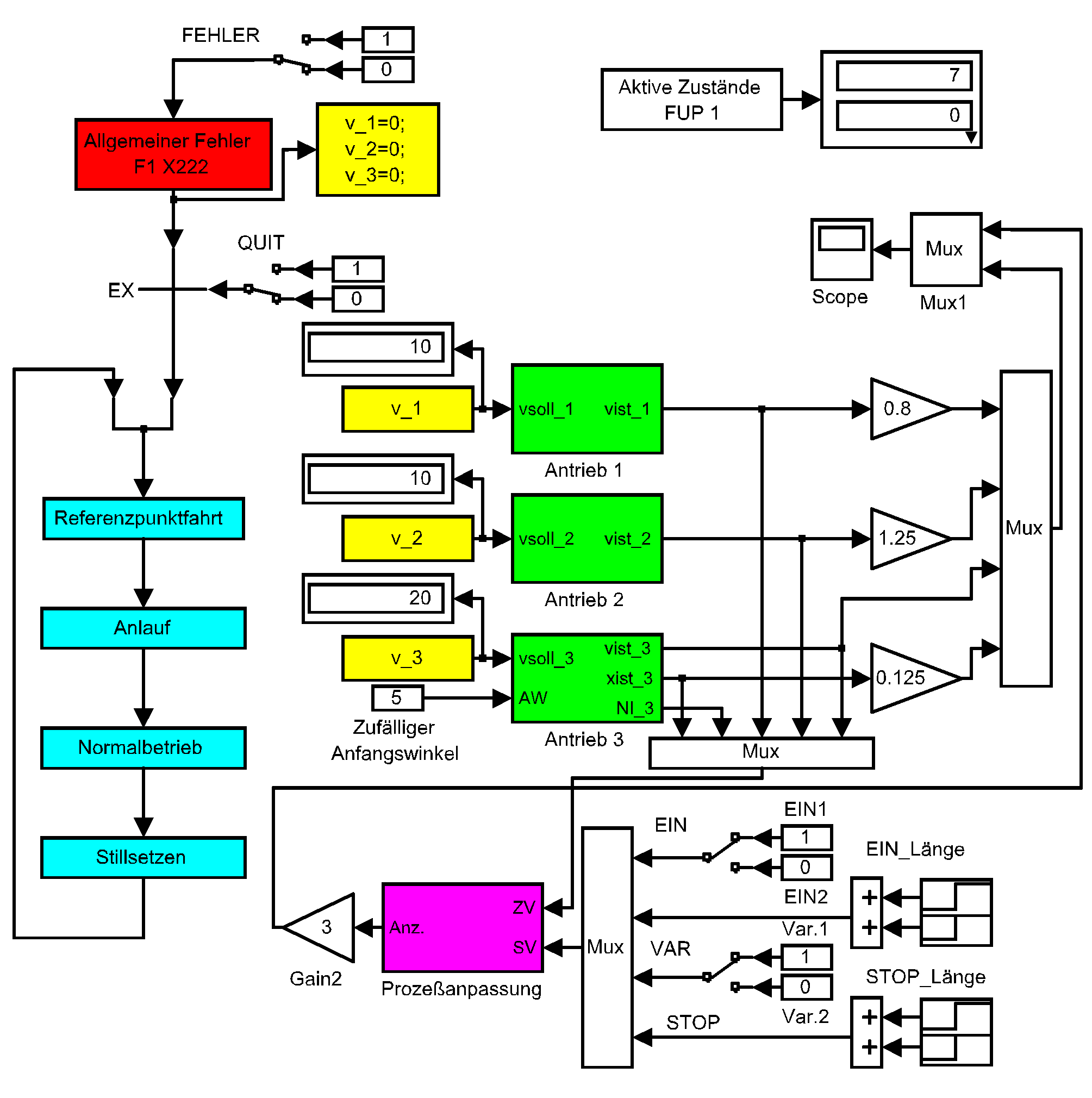
form, fill and weld machine. The overall system consists of sub function
charts, three drives, logical event equations and a group failure handling.
Four operating statuses give a rough description of the motion sequence
of the hose bag machine:
search for reference,
starting,
normal operation and
stopping.
Let us assume that the central idea of this example is the illustration
of the description and the simulation of a given motion sequence by means
of a function chart. Hence it is possible first to do without a
simulation of the mechanical subsystem and the coupling of the drives
via a material, too. According to this simplification it is only
necessary to provide the servo-controlled drives and those state
variables of the drives which are used for the event-generation - see
above.
Drive 1 corresponds to the drive of the wind-off, drive 2 corresponds to
the drive of the pull-off and the longitudinal-weld jointing-device. Both
drives provide an actual speed value (vist_1 and vist_2) each. Drive 3
corresponds to the drive of the transverse-weld jointing-device. This
drive provides an actual speed and position value (vist_3 and xist_3)
as well as an index signal (NI3). Drive 3 may start with random initial
position values (AW values from 0 to 360 degree). The reference speed
value (v_1, v_2, v_3) serves as a simplified interface of the several drives.
Since the central idea of this example is the methodical approach this is no
fatal disadvantage. A drive 4 corresponding to the drive of the dosing device
for the filler was omitted totally first. This is acceptable with respect to
the basic motion sequence study.
State X222 is a general error state. It makes it possible to simulate a
failure which causes stopping. On-line switch "FEHLER" generates the
failure and on-line switch "QUIT" acknowledges it. The reference speed value
reset serves as simplified failure handling. The use of
error pre-state
(FVZ)
blocks allows a more detailed and branched failure handling - compare
example 10.
Progression conditions for the sub function charts and a summarized verbal
description of these events are given in an event table under the subsystem
process connection.
Sub function chart
"search for reference"
realizes two variants. Activation of state X1 puts only drive 3 into operation.
The reference position will be searched backwards. The forming of
material loops is disadvantageous. Alternatively, the reference
position may be reached via state X2. In this case all three drives start
with "search speed" forward. Loss of material is the disadvantage of this
variant. Switch "EIN" allows the choice of a variant - see above.
Assuming state X12 is reached sub function chart
"starting"
realizes two variants likewise. Activation of state X15 initiates the
run-up of all drives at the same time. Drives 1 and 2 run up to the
production speed, drive 3 runs up with a higher speed up to angle 1
(welding start). A fast first welding start is the advantage of this
variant. Note that this requires a high permissible acceleration of drives
1 and 2. If this is not the case, switch "VAR" - see above - allows the
choice of a serial start-up using the states X3 and X4.
Assuming an active state X6 sub function chart
"normal operation"
is reached. The characteristic feature of this operation mode is a
persistent cycle of the states X7, X8 and X70. The
occurring of the "STOP" signal - see above - causes a transition to
state X9. Sub function chart
"stopping"
describes the subsequent motion sequence. Two parallel paths guarantee
the synchronous sequence as well of the states X10 and X11 - stopping
of drive 1 and 2, as of the states X20 and X21 - search for reference
and stopping of drive 3. After the dynamic state X15 (all drives
stopped) static state X100 (ready to start) gets active.
The sub function charts presented here are instructive in illustrating the
idea and the application possibilities of the description and the simulation
of a given motion sequence by means of a function chart. With this in mind
they cannot be considered as a standard solution in terms of technology. Thus
state X30 may be
omitted or a re-search for reference after restart of the machine
may be avoided. Each sub function chart contains sub event vectors.
However, no feedback of sub state vectors from the sub function charts to the
process connection is required for this example. This is an essential
difference to
example 8.
Owing to the switches "EIN" and "VAR" 4 different starting
sequences are possible. Any desired reference angle is adjustable in degree.
For documentation purposes of time characteristics short searches for
reference are desirable. Therefore, different "random" initial angles
should be defined for both positions of switch "EIN". Different signal
weighting factors are included for display purposes to be able to distinguish
between the technologically necessary equal production speeds of the 3 drives
- see above. The behaviour of a normal machine stop and of an
emergency stop may be studied by means of the switches "STOP" and
"FEHLER".