Block library Function Chart: library icon

german banner

Application of the add-on block library Function Chart
- all rights reserved - Dr. Geitner ETI/TU Dresden


Example 8 - Over-all system with timer

Example 8: Over-all system with timer

(sensitive)

Dynamic test with two axes of motion according to figure 3 and 4 of the VDI/VDE guide line 3684. The following motion sequence is required:
   1. state - start delay time or for several cycles:
- stop drive 2
- waiting time for drive 1
   2. state- acceleration of drive 1 in direction 1
   3. state- start of drive 2 in direction 1
- constant speed of drive 1
   4. state- braking of drive 1 to speed zero
   5. state- stop drive 2
- waiting time drive 1
   6. state- acceleration of drive 1 in direction 2
   7. state- start of drive 2 in direction 2
- constant speed of drive 1
   8. state- braking of drive 1 to speed zero
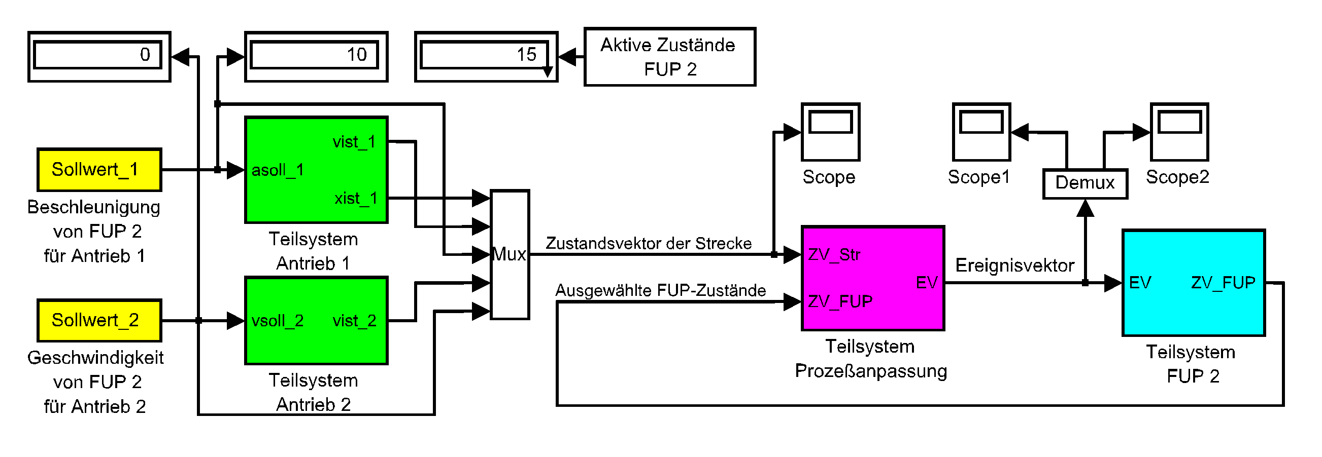
The motion of drive 1 is described by means of acceleration (a1), speed (v1) and position (x1) - the motion of drive 2 by means of speed (v2) only. Sequences with constant speed v1 shall be determined by time base - use of timer (ZG) blocks. The over-all system for the realization of this desired motion sequence consists of the subsystems drive 1, drive 2, process connection and function chart. The drive models are programmed with 40 standard blocks altogether. They contain two control loops for a cascade control structure with averaging of current and speed plus speed-proportional friction each. The digital PI controllers applied are optimized for the response to setpoint changes in the inner loops and for the response to disturbance changes in the outer loops. The outer loops include a setpoint pre-filter, too. The Digital Amount Optimum (BOD) was used as optimization rule - see Geitner, G.-H.: Entwurf digitaler Regler für elektrische Antriebe. (Design of digital controllers for electrical drives.); VDE Publishers, 1996. MATLAB m-Files for the controller parameter computation according to BOD are freely available.
The "state vector of the process" (ZV_Str) of this simple example consists of the reference and actual values of the drives 1 and 2 only. The subsystem process connection gets ZV_Str as an input signal and also the vector "selected function chart states" (ZV_FUP). On the basis of ZV_Str and ZV_FUP it generates the event vector EV as a necessary input signal for the sequencing subsystem function chart. The event vector EV contains as its elements those events which represent progression conditions for the function chart. The summarized verbal event description is given under the function chart in an event table. In the subsystem function chart the states may be connected with KB comment blocks. If the comment blocks define value assignments these definitions get valid when the belonging state gets active. "Receiver blocks" of the type FUP_V variable block receive the variables and cause switching with them in process models, motion cells, drives and so on.
The central idea of this example is the illustration of the description and simulation of a given motion sequence by means of a function chart. Hence drive control is simplified by use of abrupt changes for acceleration and speed reference values as well as of pre-breaking values.


Beginning of this web page Application examples event-driven systems Master page simulation and description of event-driven systems Master page Digital Amount Optimum (BOD) Master page Bond Graphs Chair Electric Machines and Drives