 |
FupCheck - Toolbox Function Chart Check
- all rights reserved -
Dr. Geitner ETI/TU Dresden
|
This MATLAB Toolbox allows the check of
graphically with the SIMULINK add-on library
FUP
programmed function charts to implement event-discrete time-continuous
multidimensional
motion cycles. After the function charts have been checked using this
toolbox, they can be
statically
tested with manual switch blocks or
dynamically
with
process models including digital
controllers (e.g., by means of
BOD
or EEZ)
. After that, real-time
machine codes are generated with xPC target (e.g., for embedded
controllers) and tested in the laboratory .
The test functions of the toolbox are preferably available via a GUI,
and if necessary also via m-file scripts. The scripts TEST_PARA, TEST_SYNT,
TEST_SACK, TEST_WEIT functionally correspond to the four partial
check steps described below and contain user dialogs to a small extent.
The GUI is called up by entering "FupCheck" at the MATLAB prompt.
The initial setting is the valid working directory.
The GUI start window offers three options:
- Directory selection by entering a path and drive changes
- File selection with directory tree change and complete display of
directory contents
- Function chart selection with display of the function chart number
in case a file contains several function charts
potential options:
- Test step selection with subsequent selection of parameter, syntax,
dead end or uncoupled loop check. The default is parameter check.
- Complete check with specification of all four check steps.
A subsequent click onto one of the check step buttons causes a switch onto
check step selection with specification of the selected check step.
- All analysis, hint and warning acknowledgements are outputted with comments.
- Only error messages, if there are any, and check termination are outputted
without comments.
and the control functions:
- The start button initiates the desired test step. A new GUI window
opens. This key is only released if a function chart is selected. After
the options have been changed the start button of the
GUI main window must be pressed again.
- The help key initiates the display of this text.
- The end key closes the GUI after a
safety query.
Preconditions for use of this tool are as following:
- no setting "break library link" for FUP add-on library blocks
- no use of FUP add-on library block names for subsystems
- no change of FUP add-on library block names, but prolongation permissibly
- no end of a block name via "enter" code
- no connection of FUP subsystems via tags, but FUP subsystem definition
permissibly
- no signal rounting blocks inside FUP, i.e. no Mux, Demux, Goto, From ...
- use of "mdl" extension for project files (current version)
Check possibilities: Overview

| | Parameter |

| | Syntax |

| | Dead end |

| | Arithmetic loops |

| | Complete check |
Check possibilities: Details
- Test step: Parameter
Any combinations of the following checks can be adjusted in the
GUI sub-window:
| FN - |
Do all the state blocks used have the same function chart
number that has been selected in the
GUI main window?
Incorrect blocks are listed.
|
| ZN - |
Do all the state blocks used in the selected function chart
have different status numbers? Incorrect blocks are listed.
|
| KB - |
Are all state blocks of the selected function chart attached
to a KB block each? Are all KB blocks connected with the
output of a state block? Incorrect blocks are listed.
|
| FVZ - |
Are the FVZ blocks used in the selected function chart attached
and parameterized correctly?
|
- Link to the enable input of an EX block
- Identity of FN with the following state block
- Use of an FN number of a different function chart in the project
- Illegal link to EX blocks of the normal sequence
- Illegal link to EX blocks not immediately after ZF block
- Use of FVZ blocks without programming of a ZF block
- Missing FVZ blocks at EX enable input immediately after ZF block
| FUV - |
Are all variables used in FUV blocks also defined in KB blocks of this
project?
After the comments are enabled in the
GUI main window, both
defined variables are listed and hints are given
that FUV blocks received several variables.
|
| VAR in KB - |
Are all variables used and defined in KB blocks of the project
also defined in VAR blocks?
For variables, which are defined in a KB block only once, a warning
will be displayed.
|
| ZN in FVZ - |
Are all state numbers of the normal sequence used in the error
handling?
|
- Listing of the error handling states
- Missing states of the normal sequence
- False state numbers that are relevant to error handling
- Nonexistent state numbers
When partial function charts are copied in different projects or also within
a project in subsystems, it is recommended to check FN and ZN .
The range of the test result output is determined within the
GUI main window via the comment options.

- Test step: Syntax
To display incorrect connections you can switch between "SIMULINK block
name" (default) and "block type via FN/ZN" in this
GUI subwindow. The syntax is checked
according to the VDI/VDE Guideline 3684 "Description of event-driven
motion processes by function charts":
The following syntax special cases are admissible:
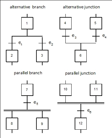
- Direct connection between
parallel
branch and junction via state blocks
- Direct connection between alternative branch and junction via EX blocks

- Test step: Dead end
The selected function chart is checked through to identify dead end
state combinations (so-called deadlocks). In this
GUI subwindow, you may switch between
the check of the first dead end (Find one) and the complete
check (Find all).
The step displays the respective number of state transitions eliminated
by reduction and compression as well as the number of states examined
afterwards, if the output of all acknowledgements is enabled
(GUI main window: With comments).
If you select "Without comments" inside the
GUI main window, you do not
disable the display of the compression cycles. The detected dead ends
are outputted line by line on the basis of sorted combinations of state
numbers (ZN).
Example - For "
b3_ko2t.mdl
" with FN=7 the following complete output is obtained:
Step 1: Analysis of function chart 7
Number of state blocks {ZA, ZX, ZE, ZF} = 13
State number of the initial state (ZA) = 100
Step 2: Check for dead ends
Number of state transitions eliminated via reduction: 1
Compression cycle 1: 1 states eliminated
Compression cycle 2: 2 states eliminated
Compression cycle 3: 1 states eliminated
Number of state blocks eliminated via compression: 4
Number of dead ends of this function chart: 1
State combinations =
30 31
Number of examined states: 120
Check completed!

- Test step: Arithmetic loops
This GUI subwindow does not contain
any other options. This check is done to uncouple arithmetic loops.
Principally, specific feedback loops may result in arithmetic loops
in any simulation or equation system. Therefore, the
use of the SIMULINK extension library Function Chart (FUP) requires that
each loop has to contain one ZA block (initial condition) or one ZE block
(state with uncoupling).
The display shows the number of the normal sequence and error sequence
paths, the total of the detected feedback paths as well as incorrect paths
if all acknowledgements (
GUI main window: With comments)
are enabled. The paths are outputted line by line in the order of the
state numbers (ZN) which are passed through.
Output example
Altogether, 3 normal sequence and 0 error sequence feedback loops were
determined.
Total of determined normal sequence loops:
| --> |
100 | 11 | 13 |
2 | 3 |
| --> |
13 | 2 | 3 |
12 |
| --> |
100 | 4 | 2 | 3 |
Warning: The following normal sequence paths contain more than one ZE
or ZA block!
| Path1 | = |
100 | 11 | 13 |
2 | 3 |
| Path2 | = |
13 | 2 | 3 |
12 |
If reduced output is selected (
GUI main window: Without comments) only
incorrect paths and a completion notice are shown.

- Complete check
The GUI subwindow does not contain any other
options. All test steps are automatically executed one after the other.
The following defaults are valid:
- Parameter: select all check steps
- Syntax: use SIMULINK block names
- Dead ends: find one dead end
- Uncoupled loops: none
The control of the display outputs via "comments" in the
GUI main window takes effect.
Each test step is numbered and terminated by an end message.


