- Requirements
Following preconditions have to be fulfilled for the design, research and
description of event-driven motion systems by means of add-on block
library Function Chart:
- Basic Software
Block library Function Chart is designed as add-on library for
Simulink. Hence software package
MATLAB/Simulink has to be installed. Other add-on block sets
and toolboxes are not necessary for application of the block library Function Chart.
- Add-on Software packages
In addition to
MATLAB/Simulink add-on
Simulink Coder
(former: RTW, Real-Time Workshop), target hardware compiler and hardware
drivers are needed for real-time code generation. In case of PC based hardware
MATLAB compiler and
xPC Target as target support
software and hardware driver library are recommended.
- Previous knowledge
The user should be familar with basic
Simulink handling.
- Activation
For add-on library Function Chart there is no installation necessary in usual
literal sense. After activation as given below all FUP library blocks are available
and of equal rank in comparison with standard libraries.
2.1 Rather up to date MATLAB/Simulink versions
File slblocks.m causes automatic integration of user library FUP into Simulink
library collection. Copy content of directory "Fup_V32" to any location on hard
disk and add at least directory "~/Fup_V32/BibV32" to MATLAB search path. After
this activity add-on library Function Chart will be ready. For rather obsolate
FUP versions please replace "V32" with "Vxy". Other useful path extentions may be
found in ReadMe.txt.
2.2 Rather obsolate MATLAB/Simulink versions
- Step 1
First use command "Unlock Library" in menu "Edit" of Simulink window "Simulink
Block Library". Then copy the icon of the add-on library Function Chart from
provided and opened file "FUP_Bibxy.mdl" to window "Simulink Block Library".
Term "xy" indicates the version number. After this new
library icon has been positioned in any desired place
close Simulink in order to lock whole "Simulink Block Library" again.
- Step 2
Make a new directory with a freely selectable name, integrate it into
MATLAB search path and copy all provided "*.dll" files into this new
directory. The number of those files varies with library version and
is specified in the provided file "readme.txt".
- Overall structure of a motion system
The overall structure for the programming of an event-driven motion
system is principally composed of the parts function chart, process
model and process connection. The function chart is conveniently
divided into sub-function charts mostly. In the simplest
case the process model consists of individual servo drives(motion
cells). Typically the overall structure may also include switches for
the control of the motion sequences (selection of variants, simulation
of errors etc) as well as blocks for display and data storage.
- Function chart / Sub-function chart
The whole functional range of a motion control may be roughly subdivided
into several operating statuses. Each operating status correlates with
a sub-function chart. Each single state of a sub-function chart transmits
control information to servo drives (motion cells) once per activation.
This is realized by
comment
blocks (
KB)
which are associated with the state blocks. The function chart receives
an event vector (EV) from the part process connection. The
subdivision of the function chart into sub function charts causes the subdivision
of EV into sub event vectors, which are assigned to the sub
function charts. According to the application a function chart may return
a state vector ZV_FUP. This vector contains selected state information
as input for the part process connection.
- Process model / individual servo drives (motion cells)
The "
FUP_V"
variable
blocks function as receivers for the individual servo drives (motion
cells). They receive and interpret the control information that is transmitted
from the function charts / sub function charts via
comment
blocks (KB).
The meaning of the information may be different depending on the drives
and motion cells used. Typical kinds of information are both binary switch
information (e.g. the start of a ramp generator with pre-defined parameters)
and continuous or discontinuous parameters (e.g. gradient and maximum value
of a ramp).
Motion processes respectively servo drives (motion cells) have to provide
a state vector of the motion sequences (ZV_Pro) for the part process
connection. Typical elements of this vector are setpoint and actual values
of position, speed and acceleration.
- Process connection
The part process connection generates the event vector EV and
the sub event vectors EV_x resp., using vector ZV_Pro and
vector ZV_FUP. As a rule the elements of ZV_Pro are combined
via Boolean equations (use of
extended
event generators, e.g.
EGE_w)
and the elements of ZV_FUP are used as start signals for the
timer
(ZG block).
- Event table
The events that are necessary for the advance within the function chart
should be collected in a clear event table, which confirms to the VDI /
VDE guideline 3684.
- Error handling for the motion process
Basically there are two ways to programme and describe error handling
sequences for event-driven motion control:
- Special error
It is useful to integrate the error handling sequence in an existing
function chart "normal operation" if the error occurs in a certain place
of the function chart only and if troubleshooting allows the continuation
of the normal operation mode.
- Common error
The common
error state block (
ZF)
handles errors which occur in any active state and cause the abort of the
normal operation mode. After activation of this block and event-dependent
branching to different error handling sequences it is possible to return
to the initial state or any other useful states. Such branching to different
error handling sequences depends on active error pre-states.
Error
pre-state blocks (
FVZ)
initiate this branching by the computation of Boolean equations.
- Block parameterization
In accordance with Simulink each block of the
block
library Function Chart is indicated by an abbreviation. These abbreviations
may be hihidden after a short time of getting familiar with the add-on
library. Mark the block and use the command "hide name" inthe format menu.
This is possible since the graphical layout is very similar to that of
the
VDI /
VDE
guideline 3684 on theone hand and the particular icon design
of the additional blocks on the other hand. These facts restrict the information
content of the graphic layout to the intrinsic functionality of the motion
sequences.
- Selection
In accordance with
Simulink
each block may be copied from the block library Function Chart to a new
window (file) as often as desired. For this purpose open the library by
a double-click on the library icon, mark the desired block and drag the
block to another screen window pressing the left mouse button, i.e. work
with "drag&drop" technique. Now connect the block inputs and outputs
again by means of the mouse. The general graphical arrangement of the blocks
can be configured freely according to individual requirements which is
especially important for branching.
- Parameterization
The double click on a block opens a special input window for that block.
It shows block name
and block description. Here you can find block-specific inputs as for
instance state and function chart number (
ZX
state
blocks), string variables and initial values (
FUP_V
variable blocks) or time values (
ZG timer
blocks). Click onto help in that window for detailed on-line
block
help via Netscape Navigator. This help text offers all necessary information
for the application of the particular block, as e.g. application conditions,
data for input and output or limit conditions for the input.
- Standard blocks
The design details of the servo drives (motion cells) in
Simulink
are completely ignored here. For such details use the standard libraries,
e.g. Discrete, Linear or Non-linear plus the Power System Blockset. It
is characteristic to use dedicated standard blocks for the application
of the add-on library
Function Chart. Compare the 11
examples too. These standard blocks and their tasks are:
- Mux: grouping of scalars and / or vectors to vectors
- Demux: degrouping of vectors to scalars and
/ or vectors
- Display: display the numerical values of scalars
and / or vectors
- Scope: measurement and display (with magnifier function) of curve
shapes; generation of time sequence charts for documentation
- Constant: source of scalars and vectors for
test and switch tasks
- Digitel Clock: discrete time output - count pulses for
timer
(ZG)
- Konnektoren: invisible connection of block inputs
and outputs
- Manual Switch: on-line switching with the
mouse for test and switch tasks
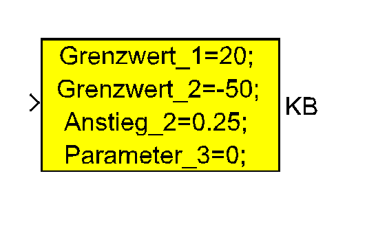
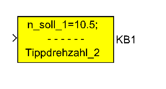
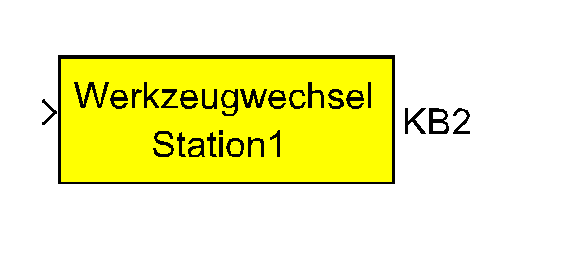
- Comment block
The KB
comment
block is the only one of the
block
library Function Chart which can appear in different icon forms:
- exclusively value setting
|
- value setting and comment text
|
|
 |
 |
 |
- State display
There are two ways to display active states of a function chart:
- Display of all active states of one function chart
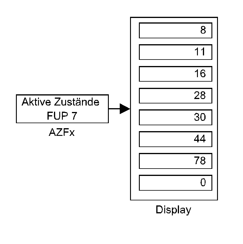
This method implies the smallest effort. Select a block
AZFx
"Active
States", set the required function chart number and connect this block
to a "Display" block. Repeat this for any function
chart you want to observe. Note that presently the number of displayable
states has to be set as a fixed value because of a
Simulink
error. The fixed number of 7 states may be changed on demand and queries.
- Display of selected states, even of different function charts
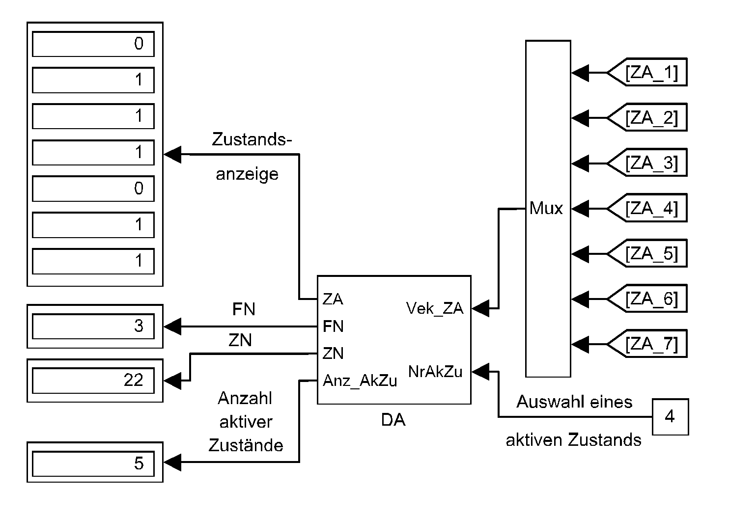
Group the interesting state block outputs to a vector and connect it
to input Vek_ZA of DA
block "Decoding
of the Display". That block provides the corresponding binary state
information at its output ZA and the sum of all active interessting states
at output Anz_AkZu. The selection of one of these active states via connection
of its element number in vector Vek_ZA to input NrAkZu cause the output
of the associated function chart and state number at the outputs FN and
ZN. The first element number is 1 according to MATLAB conventions.
- Test
After a function chart has been designed and programmed test it statically
without any process model and process connection first of all. The process
models that will be necessary for the following dynamic test of the function
chart should be sufficiently verified at this time, however.
- Static test
It is necessary to simulate the progress events of function charts
for the implementation of static tests of function charts. Use "
Constant"
blocks whose elements are directly alterable during a simulation run or
"Manual Switch" blocks whose inputs are connected
to a "Constant" scalar block containing "1" or "0"
each as an event generator.
In the first case group ("MUX" block) the events in vectors for better
transparency. To feed an event to an
event
block ("EX"
block) degroup the particular vector ("DEMUX" block)
and use connectors ("GoTo" and "From" blocks), i.e.
that here the number of "Constant" blocks may absolutely
fall below the number of events. In the second case the required number
of "Manual Switch" blocks corresponds to the number
of events. The same number of "Constant" scalar blocks
containing "1" respectively "0" is necessary, in addition. Reset the events
immediately after the activation of a new state during the test. Doing
this you can be sure to keep track of the system as a whole as well as
to avoid errors resulting from this test. Be sure to use the adjustment
"Stop time = inf" in the "simulation / parameters / solver" menu for static
tests.
- Dynamic test
For dynamic tests of function charts it is necessary to generate the
events from time-dependent state vectors of the motion sequences (
ZV_Pro)
which are understood to be variable. Make sure that the events have a certain
minimal length and are reset in time. For this purpose
event
generator blocks have been developed , e.g.
EG_w.
One event block ("EX"
block) with a static event signal can be placed between two
event
blocks ("EX"
blocks) with dynamic event signals. Realize the selection of variants in
that way. For this purpose and for the implementation of start /
stop switches as well utilize the "Manual Switch" blocks with "
Constant"
scalar blocks containing "0" and "1" at its inputs (for the "
Manual
Switch" blocks see chapter static test).
- Real-time code generation
With version 3.0 and later of the block library Function Chart a graphically
programmed motion control can be translated into the programming language
"C". On condition that conformed "C" compilers are available the real-time
code generation for different hardware platforms is possible. The only
thing the user has to do is to register all Function Chart library files
"*.lib" in his Target Support Software. Existing make-files can be used
further.
MATLAB/Simulink
offers a tool for the design of user interfaces if the Target Support Software
supports an on-line data transmission between host and target in both directions.
As a rule in most cases oscilloscopes become unnecessary then since the
Target Support Software provides scope functions that are typically comprehensive.
Provided the communication within the designed motion control is based
on a fast bus system device-internal data (e.g.data of servo drives or
programmable controllers) are quite as well visualizeable together with
events and process state signals.
Assuming that the technology of the motion process tolerates it the
real-time use of
Simulink
standard on-line switches "Manual Switch" for event
simulations allowes to employ the stepping mode to a certain or the full
extent. The design of hierarchical systems is possible as well depending
on the technology and / or the device technique.
- Documents
An introduction with summary of essential features and application notes,
as well as description of selected examples and block descriptions in
tabular form is available as
PDF document for the obsolete version 2.3.
Whereby the info in the subsections "Software" and "Installation" of this
PDF documentation is accordingly not valid for the current v ersion 3.2
- see info under "2. Activation" above.
